
Hello,
I am using Labview 16 with a Labjack U6 to communicate with a pressure sensor (LMI). When running my program I don't get any error message but I am not getting measures from the sensor.
Here are a few infos on my setup :
Normal 0 21 false false false FR X-NONE X-NONE /* Style Definitions */ table.MsoNormalTable {mso-style-name:"Tableau Normal"; mso-tstyle-rowband-size:0; mso-tstyle-colband-size:0; mso-style-noshow:yes; mso-style-priority:99; mso-style-parent:""; mso-padding-alt:0cm 5.4pt 0cm 5.4pt; mso-para-margin-top:0cm; mso-para-margin-right:0cm; mso-para-margin-bottom:8.0pt; mso-para-margin-left:0cm; line-height:107%; mso-pagination:widow-orphan; font-size:11.0pt; font-family:"Calibri",sans-serif; mso-ascii-font-family:Calibri; mso-ascii-theme-font:minor-latin; mso-hansi-font-family:Calibri; mso-hansi-theme-font:minor-latin; mso-bidi-font-family:"Times New Roman"; mso-bidi-theme-font:minor-bidi; mso-fareast-language:EN-US;}
- Pin 5, 6 and 3 of the sensor are connected to the labjack Ground => 7-bit I2C address is 1011100 (0x5C) (page 8/17). After the shifting, the 8 bit address that I use in my code is 10111000
- AO0 is set to 3.3V. The VS input of the sensor is connected to the AO0 output for powering. Cheked the voltage on the sensors pins, it’s ok.
- A 4.7kOhms resistance is connected between SDA pin and Vs.
- A 4.7kOhms resistance is connected between SCL pin and Vs.
The data sheet of the sensor explaining how to communicate with the sensor can be fined here : https://www.first-sensor.com/cms/upload/datasheets/DS_Standard-LMI_E_118...
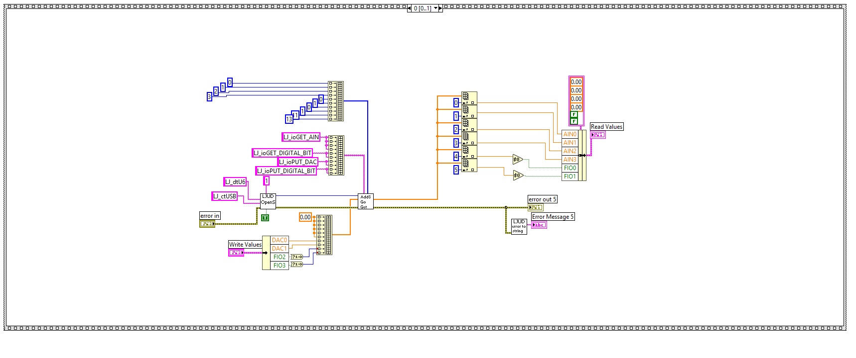
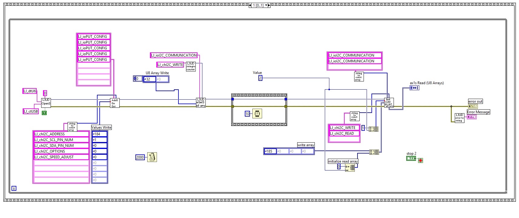
I have attached a Labview 8.0 version of the program. And also 2 print screens of the program in case you can't open it.
Can you see what I am doing wrong?
Thank you very much.
Best regards,
User

.png%3Fitok=PHGBxf6M "EEV Blog Reviews LabJack T7-Pro & Software Tools")


.jpg%3Fitok=B1YcuDFK)
.png%3Fitok=Ybt-OlgU "LabJack + JEDI One Can Create a Powerful Distributed DAQ Ecosystem")
I am not able to open your VI, but I do see a couple potential issues in the block diagram screenshots. The first is that the IO lines are set to 0 and 1. We recommend using EIO for serial communication because it has less impedance. The second issue is that the speed is set to zero, it is usually a good idea to start with the clock speed set low and the raise it after everything is working. 10 kHz is a good starting place. The lower clock speed may also help when using FIO lines.
Also, have a look at our I2C app-note. It contains a lot of good advise that will help you avoid common I2C pitfalls. The acknowledgement reporting may be useful.
If that doesn't help we may need an oscilloscope or logic analyzer.
Hello,
I have switched over to the EI00 and EI01 pins, and set the speed to the lowest value (255) but I still don't get any measures back.
There could be some clock streching or other subtilities that may take too much time for me to solve.
I will look for other solutions.
Thank you for your help.
User
Did you check the acknowledgements (LJ_chI2C_GET_ACKS)?
That will tell you if the slave device is respond at all. If not problems are likely hardware or the address value. If it is responding to its address then our problem is in the usage of the slave device.
Hi,
When running the program (screenshot) I get Numbers of Ack's = 3 at the first loop (but no measures) . After first loop, it changes to 0 (no measures).
I got a second pressure sensor that runs ok with Arduino. The program is really simple, for each loop :
I send the sensor's address : 0x5c
I send the 0x20 command to tell the sensor to make a measurement
I ask for a 2 bytes read
I have attached the VI in 8.0 version in case you succeed in opening it.
The Acks is good news. That means that both the address and the command byte were acknowledged.
Looking at the VI diagram, I think we need to move GET_ACKS to a separate call after the the add-go-get that runs LJ_chI2C_WRITE and LJ_chI2C_READ. The driver might be correcting that for us, but I am not sure.
If that doesn't help we can try the compatibility options. Try changing the options byte to:
Hello,
Your advice worked out, thanks a lot!
It's now working with the setup that you can see on the screen shot (Get_acks moved as a seperate call and Options set to 12). If Get_acks is not moved, changing the options doesn't make things work.
I have two other questions :
1) I don't understand how Get acks adds up the Acks, since when ?
- If Get_Acks is not a seperate call, I get no measurement but get Acks = 3
- if I call Write then Get_Acks at the time and Read separately, I get the correct measurements, and get acks = 3
-if only Get_Acks is seperate, I get the correct measurements and get acks = 1
2/I have put 4 of these sensors (each have their own adddress) on line EI0 and EI1
I have put 4 of these sensors (each have their own adddress) on line EI2 and EI3
I was planning to get the measurement of those two I2C pair of lines in parrallele. Can you confirm it is not possible? When doing that, I only get measurement from one pair of lines. the other one outputs the measurements from the other pair.
Thanks.
User
1) Every transmitted byte is represented by a bit in the ACK array. A 3 in binary is 0b00000011, which would mean that two bytes were acknowledged.
"If Get_Acks is not a seperate call..." The Get_Acks was between the transmit and receive operations. So, I think the request to read ACKs was terminating the I2C operation before the reads could run. Separating out the read and write operations would would because that would run two separate I2C operations one to write and one to read.
2) The U6 can run multiple I2C buses. The only limitation is that only one can be actively clocking at any give time.
Hi ,
I know this post is very old but I have a quick question about sending commands to I2C Slave using LabJack U6.
I want to control an STM32F10X MicroController using I2C through LabJack. Im able to connect to this chip using arduino Wire.h.
In arduino, we have the option of sending strings as commands to the I2C slave. How do I send string commands like *IDN? to I2C slave through LabJack. Do I have to treat each character as a byte, convert to dec and send it?
Also, Is there a way to scan for list of all connected I2C devices without mentioning the address?
Any help woul be greatly appreciated.
Thank you
Hello,
I believe we talked over chat, but I wanted to follow up here in case it is useful for anyone else.
You will need to send the string as an array of bytes. I would recommend explicitly converting your characters to decimal or hex representations of the associated ASCII values before sending out your command.
I do not think we have anything explicitly implemented for the U6 that will scan for valid I2C devices, but one thing you could do is iterate through a range of potential addresses and try a dummy read/write and check for ACKS for each address. You could probably set that up pretty easily with Read_GetAcks_and_Write.vi