
Hi everyone,
I try to read and write the digital potentio (MCP4661) using T7 and LJM_2019_04_03, the communication is use i2c. with same setting, i has done to comunicate with other chip (PCF8574 expander i/o). Its somebody has experience with MCP4661?
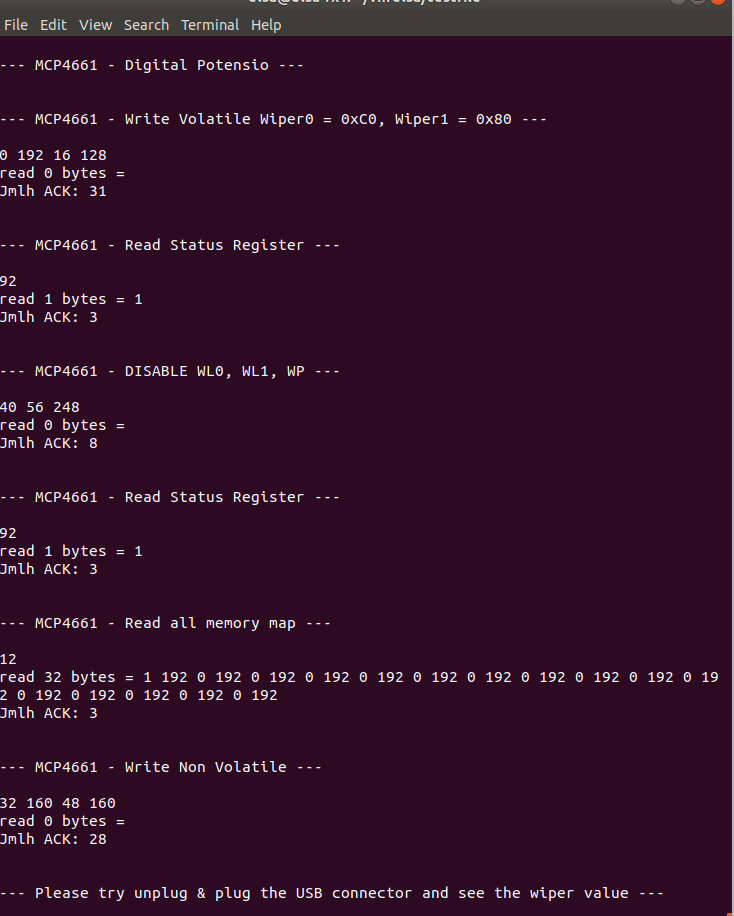
Please find my code, screen capture of my output result (t7_i2c_mcp4661.png) and some digital logic analyzer at attached.
What i make it strange is:
1. On first code after initialize, i try to write volatile register of Wiper0 and Wiper1. The Wiper value is change when i read using ohm meter. But the sum of ACK is bigger then my expectation, its print out 31. I am write 4 byte and without read, it must be 4 ACK right? see my logic analyzer screen capture (i2c_t7_mcp4661_1.png)
2. on second block, i try to read, write and read again the non volatile memory. On first read, i got value is 1 with sum of ACK is 3. i read only 1 byte but i got 3 ACK (i2c_t7_mcp4661_2.png). After that i write the new value (i has try to change the value for enable and disable, but no change) = 0x28, 0x38, 0xF8. on here, i got ACK is 8 and on my logic analyzer, first and second byte is have NACK (i2c_t7_mcp4661_3.png). After that i try to read the register again, the value is not change, is still 1 with ACK is 3 (i2c_t7_mcp4661_4.png)
3. on third block i try to read out all register. the value what i get is strange only 0 or 192 with ACK is only 3
4. on last block i try to write 4 bytes the non volatile register. What i make it doubt, the ACK is 28. And after restart power, the wiper is not change to my new value. The wiper is still on factory value, on midle
Its any my code is mistake? i hope i can get help on this forum. Many thanks

.png%3Fitok=PHGBxf6M "EEV Blog Reviews LabJack T7-Pro & Software Tools")


.jpg%3Fitok=B1YcuDFK)
.png%3Fitok=Ybt-OlgU "LabJack + JEDI One Can Create a Powerful Distributed DAQ Ecosystem")
Hi everyone,
i found my mistake for item 3. When i am read out all register, i am not yet prepare the variable for 32 byte array. I has add it but the result all value is 0 with ACK is only 3. See my attached file
I am very appreciate if you can suggest me what i need to try it as solution. Many thanks
There aren't any LabJack'ers who are currently experts regarding your particular I2C chip. Good news on you solving your mistake for number 3.
It looks like your issue may be due to not properly dynamically allocating an array in python.
SOLVE
when need to write or read, its ok when read/write every 1 register address. Here my code for testing
"""
Demonstrates I2C communication using a LabJack. The demonstration uses a
MCP4661 connected to FIO0/FIO1 for the T7 or FIO4/FIO5 for the T4, and
configures the I2C settings. Then a read, write the Digital Potentio
registered.
"""
from random import randrange
from labjack import ljm
import time
# Open first found LabJack
#handle = ljm.openS("ANY", "ANY", "ANY") # Any device, Any connection, Any identifier
handle = ljm.openS("T7", "ANY", "192.168.3.7") # T7 device, Any connection, Any identifier
#handle = ljm.openS("T4", "ANY", "ANY") # T4 device, Any connection, Any identifier
#handle = ljm.open(ljm.constants.dtANY, ljm.constants.ctANY, "ANY") # Any device, Any connection, Any identifier
info = ljm.getHandleInfo(handle)
print("Opened a LabJack with Device type: %i, Connection type: %i,\n"
"Serial number: %i, IP address: %s, Port: %i,\nMax bytes per MB: %i" %
(info[0], info[1], info[2], ljm.numberToIP(info[3]), info[4], info[5]))
deviceType = info[0]
# Configure the I2C communication.
if deviceType == ljm.constants.dtT4:
# Configure FIO4 and FIO5 as digital I/O.
ljm.eWriteName(handle, "DIO_INHIBIT", 0xFFFCF)
ljm.eWriteName(handle, "DIO_ANALOG_ENABLE", 0x00000)
# For the T4, using FIO4 and FIO5 for SCL and SDA pins. FIO0 to FIO3 are
# reserved for analog inputs, and digital lines are required.
ljm.eWriteName(handle, "I2C_SDA_DIONUM", 5) # SDA pin number = 5 (FIO5)
ljm.eWriteName(handle, "I2C_SCL_DIONUM", 4) # SCL pin number = 4 (FIO4)
else:
# For the T7 and other devices, using FIO0 and FIO1 for the SCL and SDA
# pins.
ljm.eWriteName(handle, "I2C_SDA_DIONUM", 1) # SDA pin number = 1 (FIO1)
ljm.eWriteName(handle, "I2C_SCL_DIONUM", 0) # SCL pin number = 0 (FIO0)
# Speed throttle is inversely proportional to clock frequency. 0 = max.
ljm.eWriteName(handle, "I2C_SPEED_THROTTLE", 65536) #65516) # Speed throttle = 65516 (~100 kHz)
# Options bits:
# bit 0: 1 = Reset the I2C bus before attempting communication.
# bit 1: 0 = Restarts will use a stop and a start, 1 = Restarts will not use a stop.
# bit 2: 1 = disable clock stretching.
ljm.eWriteName(handle, "I2C_OPTIONS", 2)
# ---------------------------------------- MCP4661 ----------------------------------------
# value : 0 --> Raw = 8k8, Rbw = 93ohm
# value : 255 --> Raw = 131ohm, Rbw = 8k8
# Ra --vvv- Rw -vvv-- Rb
print("\n--- MCP4661 - Digital Potensio ---\n")
# labjack.com/support/datasheets/t-series/digital-io/i2c/i2c-simulation-tool
# Ad3_Ad2_Ad1_Ad0__A2(pin 12)_A1(pin 13)_A0(pin 1)_x
# I2C address need to right shift 1 bit (ox52 >> 1 = 0x29)
addwDigPot = 0x29
ljm.eWriteName(handle, "I2C_SLAVE_ADDRESS", addwDigPot)
# Memory map address
aregVolWiper0 = 0
aregVolWiper1 = 1
aregNonVolWiper0 = 2
aregNonVolWiper1 = 3
aregTCON = 4
aregStatus = 5
aregWP = 0xF
def prReg(addReg):
if addReg == aregVolWiper0:
print(" Wiper 0\n")
elif addReg == aregVolWiper1:
print(" Wiper 1\n")
elif addReg == aregNonVolWiper0:
print(" Wiper Lock 0\n")
elif addReg == aregNonVolWiper1:
print(" Wiper Lock 1\n")
elif addReg == aregTCON:
print(" TCON\n")
elif addReg == aregStatus:
print(" Status\n")
elif addReg == aregWP:
print(" Write Protect\n")
else:
print(" - Unknown Register: %i\n" % addReg)
def mcpWrite(addReg, wVal):
b1 = (addReg << 4) | 0
tmpW = (wVal & 0x0100) / 256
b1 |= tmpW
b2 = wVal & 0x00FF
numBytesTx = 2
numBytesRx = 0
aBytes = [b1, b2]
#print("Write : ")
prReg(addReg)
print("%s" % " ".join([("%.0f" % val) for val in aBytes]))
ljm.eWriteName(handle, "I2C_NUM_BYTES_TX", numBytesTx) # Set the number of bytes to transmit
ljm.eWriteName(handle, "I2C_NUM_BYTES_RX", numBytesRx) # Set the number of bytes to receive
ljm.eWriteNameByteArray(handle, "I2C_DATA_TX", numBytesTx, aBytes)
ljm.eWriteName(handle, "I2C_GO", 1) # Do the I2C communications.
aBytes = ljm.eReadNameByteArray(handle, "I2C_DATA_RX", numBytesRx)
jmlhack = ljm.eReadName(handle, "I2C_ACKS")
print("Jmlh ACK: %i\n" % jmlhack)
def mcpRead(addReg):
b1 = (addReg << 4) | 0x0C
numBytesTx = 1
numBytesRx = 2
aBytes = [b1, 0]
#print("%s" % " ".join([("%.0f" % val) for val in aBytes]))
ljm.eWriteName(handle, "I2C_NUM_BYTES_TX", numBytesTx) # Set the number of bytes to transmit
ljm.eWriteName(handle, "I2C_NUM_BYTES_RX", numBytesRx) # Set the number of bytes to receive
ljm.eWriteNameByteArray(handle, "I2C_DATA_TX", numBytesTx, aBytes)
aBytes = [0] * numBytesRx
aBytes = ljm.eReadNameByteArray(handle, "I2C_DATA_RX", numBytesRx)
ljm.eWriteName(handle, "I2C_GO", 1) # Do the I2C communications.
tmpW = (aBytes[0] << 8) + aBytes[1]
print("read %i bytes = %s" %
(numBytesRx, " ".join([("%.0f" % val) for val in aBytes])))
jmlhack = ljm.eReadName(handle, "I2C_ACKS")
print("Jmlh ACK: %i\n" % jmlhack)
print("tmpW: %i\n" % tmpW)
return tmpW
def mcpUp(addReg):
b1 = (addReg << 4) | 0x04
numBytesTx = 1
numBytesRx = 0
aBytes = [b1]
print("Incr ")
prReg(addReg)
ljm.eWriteName(handle, "I2C_NUM_BYTES_TX", numBytesTx) # Set the number of bytes to transmit
ljm.eWriteName(handle, "I2C_NUM_BYTES_RX", numBytesRx) # Set the number of bytes to receive
ljm.eWriteNameByteArray(handle, "I2C_DATA_TX", numBytesTx, aBytes)
ljm.eWriteName(handle, "I2C_GO", 1) # Do the I2C communications.
aBytes = ljm.eReadNameByteArray(handle, "I2C_DATA_RX", numBytesRx)
jmlhack = ljm.eReadName(handle, "I2C_ACKS")
print("Jmlh ACK: %i\n" % jmlhack)
def mcpDown(addReg):
b1 = (addReg << 4) | 0x08
numBytesTx = 1
numBytesRx = 0
aBytes = [b1]
print("Decr ")
prReg(addReg)
ljm.eWriteName(handle, "I2C_NUM_BYTES_TX", numBytesTx) # Set the number of bytes to transmit
ljm.eWriteName(handle, "I2C_NUM_BYTES_RX", numBytesRx) # Set the number of bytes to receive
ljm.eWriteNameByteArray(handle, "I2C_DATA_TX", numBytesTx, aBytes)
ljm.eWriteName(handle, "I2C_GO", 1) # Do the I2C communications.
aBytes = ljm.eReadNameByteArray(handle, "I2C_DATA_RX", numBytesRx)
jmlhack = ljm.eReadName(handle, "I2C_ACKS")
print("Jmlh ACK: %i\n" % jmlhack)
# ------------------------- Write Volatile Memory Add (0h, 1h, 4h) -------------------------
# AD3 AD2 AD1 AD0 Cmd1 Cmd0 x D8 --> 4 bit pd hight byte sbg Address memory map,
# Cmd1:0 = 00 --> Write
# Cmd1:0 = 01 --> Increment
# Cmd1:0 = 10 --> Decrement
# Cmd1:0 = 11 --> Read
# Volatile Wiper0 (00h) = 0xC0
# Volatile Wiper1 (10h) = 0x80
# Volatile TCON (40h) = no change
print("\n--- MCP4661 - Increment Volatile Wiper0 & Decrement Wiper1 ---\n")
# change to new value
newval = 0
print("Wiper0 change to midle value")
mcpWrite(aregVolWiper0, newval)
time.sleep(3)
print("Wiper1 change to midle value")
mcpWrite(aregVolWiper1, newval)
time.sleep(3)
# Step by step (incr/decr)
print("incr/decr step by step every second")
for i in range(10):
mcpUp(aregVolWiper0)
mcpUp(aregVolWiper1)
time.sleep(1)
# ----------------------- Read Status Register (5h + cmd1:0=Ch --> 5Ch) -----------------------
# x x x x EEWA WL1 WL0 WP
# EEWA --> EEPROM Write Active status bit (1 = Write cycling is currently occuring)
# WL1 --> WiperLock Status bit for Resistor Network 1 (1 = Write protected)
# WL0 --> WiperLock Status bit for Resistor Network 0 (1 = Write protected)
# WP --> EEPROM Write Protect Status bit (1 = EEPROM Write protected)
wTCON = mcpRead(aregTCON)
print("Read TCON Register \n")
wStatus = mcpRead(aregStatus)
print("Read Status Register \n")
print("TCON: %i , Status: %i \n" % (wTCON, wStatus))
# ----------------------- Disable WL0, WL1, WP -----------------------
# Add DecrCmd(x8h) IncrCmd(x4h)
# 2xh WL0 Enable WL0 disabled
# 3xh WL1 Enable WL1 disabled
# Fxh WP Enabled WP disabled
print("\n--- MCP4661 - DISABLE WL0, WL1, WP ---\n")
mcpUp(aregNonVolWiper0)
mcpUp(aregNonVolWiper1)
mcpUp(aregWP)
# ----------------------- Read Status Register (5h + cmd1:0=Ch --> 5Ch) -----------------------
# x x x x EEWA WL1 WL0 WP
# EEWA --> EEPROM Write Active status bit (1 = Write cycling is currently occuring)
# WL1 --> WiperLock Status bit for Resistor Network 1 (1 = Write protected)
# WL0 --> WiperLock Status bit for Resistor Network 0 (1 = Write protected)
# WP --> EEPROM Write Protect Status bit (1 = EEPROM Write protected)
wTCON = mcpRead(aregTCON)
print("Read TCON Register \n")
wStatus = mcpRead(aregStatus)
print("Read Status Register \n")
print("TCON: %i , Status: %i \n" % (wTCON, wStatus))
# ----------------------- WRITE Non Volatile Wiper0 (20h) & Wiper1 (30h) -----------------------
print("\n--- MCP4661 - Write Non Volatile ---\n")
newval = 128
mcpWrite(aregNonVolWiper0, newval)
print("--- Write Non Volatile Wiper0 = %i" % newval)
wpr = mcpRead(aregNonVolWiper0)
print(" Read Wiper0: %i\n" % wpr)
mcpWrite(aregNonVolWiper1, newval)
print("--- Write Non Volatile Wiper1 = %i" % newval)
wpr = mcpRead(aregNonVolWiper1)
print(" Read Wiper1: %i\n" % wpr)
# ----------------------- Enable WL0, WL1, WP -----------------------
# Add DecrCmd(x8h) IncrCmd(x4h)
# 2xh WL0 Enable WL0 disabled
# 3xh WL1 Enable WL1 disabled
# Fxh WP Enabled WP disabled
print("\n--- MCP4661 - ENABLE WL0, WL1, WP ---\n")
mcpDown(aregNonVolWiper0)
mcpDown(aregNonVolWiper1)
mcpDown(aregWP)
# ----------------------- Read Status Register (5h + cmd1:0=Ch --> 5Ch) -----------------------
# x x x x EEWA WL1 WL0 WP
# EEWA --> EEPROM Write Active status bit (1 = Write cycling is currently occuring)
# WL1 --> WiperLock Status bit for Resistor Network 1 (1 = Write protected)
# WL0 --> WiperLock Status bit for Resistor Network 0 (1 = Write protected)
# WP --> EEPROM Write Protect Status bit (1 = EEPROM Write protected)
wTCON = mcpRead(aregTCON)
print("Read TCON Register \n")
wStatus = mcpRead(aregStatus)
print("Read Status Register \n")
print("TCON: %i , Status: %i \n" % (wTCON, wStatus))
# ----------------------- Read all memory map -----------------------
print("\n--- MCP4661 - Read all memory map ---\n")
numBytesRx = 16
aWord = [0] * numBytesRx
x = 0
for x in range(16):
aWord[x] = mcpRead(x)
print("read %i bytes = %s" %
(len(aWord), " ".join([("%.0f" % val) for val in aWord])))
print("\n--- Please try unplug & plug the USB connector and see the wiper value ---\n")
# Close handle
ljm.close(handle)