
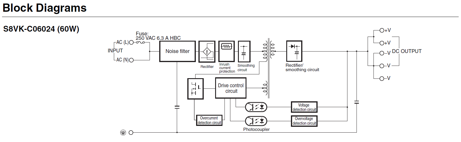
I will connect two pressure transducers (24 VDC input, 0-10VDC output) to a regulated AC/DC converter and connect the analog lead of each to a LabJack T7. What is the best way to make the common connection between the negative of the 24 VDC supply, the pressure transducers and the LabJack? Should I connect to the SGND or to GND with a 100 ohm resistor? Is there any issue with the type of power supply I am using (attached the block diagram)? Thanks for any support you can provide.
File Attachment:

.png%3Fitok=PHGBxf6M "EEV Blog Reviews LabJack T7-Pro & Software Tools")


.jpg%3Fitok=B1YcuDFK)
.png%3Fitok=Ybt-OlgU "LabJack + JEDI One Can Create a Powerful Distributed DAQ Ecosystem")
Your diagram looks good, but I suggest you connect DC- to T7-GND, rather than T7-SGND.
The power supply DC outputs are isolated from the AC side, so no issue of ground loops or strange common-mode voltages.
The signals are single-ended referred to DC- (from how it looks on your diagram), and you are doing a single-ended measurement, so you don't want any voltage difference between DC- and T7-GND.
Great! Thanks for the speedy reply.
To the setup above, I have added two sensors. I am making a differential measurement across the two sensors, but I have determined that the pressure transducer power supply is adding a few mV of noise to the measurement on the sensor. I thought that the differential measurement would not be as affected because it is not using the GND, but even after ensuring everything is well shielded and even physically isolated, there is still 3 or 4 mV of noise from the power supply.
Do you have any recommendations on isolating the signal on the sensors for the differential measurement? [for ex. AIN10 as (+) and AIN11 as (GND reference)]
I am considering the purchase of a different power supply with an improved isolation, but I would like to here any advice on alternative methods to resolve this issue if you have any.
Thanks.
Are your pressure transducers expected to have poor line regulation? Perhaps post a link to specs for your sensors.
Are you doing something different compared to your original diagram? Perhaps attach an updated diagram.
Are you measuring each sensor differentially, or doing a single differential measurement of the difference of SignalP1 and SignalP2?
Here's the updated schematic, a very simple change. There's really nothing in the pressure transducer spec sheet about line regulation, not really any electrical characteristics except the expected response etc.
The new sensors are passive electrodes expected to measure between +/- 100 mV or so.
I was thinking to take a differential measurement on the pressure transducers as well, which would avoid the need for a ground reference, but then I would not have an independent pressure for each only the difference between the two pressure sensors. Additionally, each has a slightly different calibration that needs to be applied.
It looks like AIN10 & 11 are floating, which could be your problem. Are these actually each singular electrodes with a single wire, or typical electrode sensors with a sense wire and reference wire? If they are singular electrodes, then your connections might be fine if you just add a resistor from AIN10 to GND. 100k would be typical, but you could use even larger if you want. The resistor provides a path for bias currents and defines the voltages compared to T7-GND.