
Hi All,
I'm hoping to use the U3 low voltage Labjack model as a DAQ for power measurement of an entire breaker box. I will install a current transformer coil (CT) on the wire leaving each breaker (such as this one: http://www.digikey.com/product-detail/en/talema-group-llc/AC1050/1295-11...).
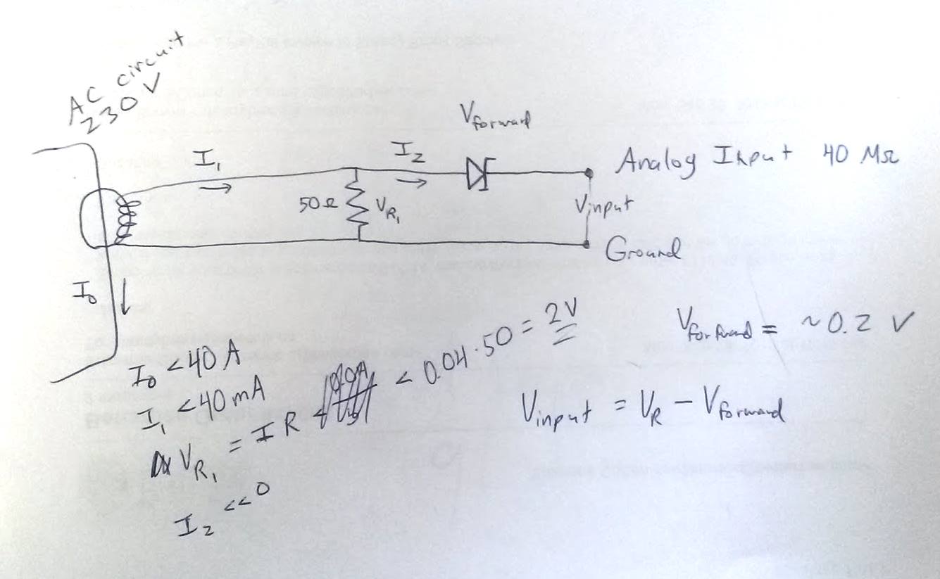
The CT must be terminated through a resistor to create a reasonable voltage to measure. However, the voltage across the resistor will be AC and will need to be rectified in order to input into the 0-2.4 DC analog inputs. I could use a half or full wave rectifier, but will need to use Schottky diodes to get the lowest possible forward voltage drop. The voltage drop will affect the lowest possible current that I will be able to measure. I don't need great precision or the need to detect small loads; I'll be measuring fairly large currents running to big machines, so I think this is ok.
Does anyone have any experience with this? Am I on the right track or out to lunch?
The inputs have very high impedance (40 Mohm) so they won't sink much current. Can I get away with just a half wave rectifier and a capacitor to smooth the voltage? Do I even need the cap?
I haven't bought the daq yet but I like what I am reading here on this website. Thanks for your help.
John

.png%3Fitok=PHGBxf6M "EEV Blog Reviews LabJack T7-Pro & Software Tools")


.jpg%3Fitok=B1YcuDFK)
.png%3Fitok=Ybt-OlgU "LabJack + JEDI One Can Create a Powerful Distributed DAQ Ecosystem")
A rectifier as you describe is not super accurate, but sounds like it might be fine for your needs. It can be tough to filter 60 Hz with a simple RC filter, but if you use a max series resistor (10k or 200k per Appendix A) and then a big cap you again will probably get something that meets your needs.
Another consideration is to acquire the bipolar signal on one of the +/-10V inputs on the U3-HV, fast enough that you get say 100 samples/cycle, and then do math in software to get the value you want (e.g. RMS).
Another consideration is to use the T7 which has an RMS feature:
https://labjack.com/support/datasheets/t7/ain/extended-features/rms
This RMS feature will likely be available on future lower cost T-series devices also, like the T4 (~early 2017) which is similar to a U3-HV with Ethernet.
Thank you! I was thinking the HV option with software RMS looked good, but then I noticed that only the first four inputs can handle the negative voltage. Handling the RMS calculation will make things harder too since software is not my strong point, so I'm going to stick with the rectifier for now.
If I increase my resistor size to create a higher voltage, I can detect current above 1 or 2 amps (good enough to detect the motors I'm using). I'm assuming I can find a diode with 0.2-0.4V forward voltage.
For the rectifier circuit, are you saying I would put the signal through the diode, then a large (1 k ohm) resistor in series, and then connect to a cap (which is grounded) and then to the input? Or is the resistor in between the input and the cap?
Also looking forward to the T4 next year.
I think you need a parallel load resistor 1st to give you a voltage signal. Then the series diode. Then a series resistor (RC filter resistor) to the low-voltage analog input FIO4, and also a capacitor (RC filter cap) from FIO4 to GND.
I would choose the series resistor to be as big as possible (10k or 200k per Appendix A) and then choose a cap. For example, if Rf=10k and Cf=10uF the cutoff frequency is 1.6 Hz. That will get rid of some of your 60 Hz but maybe not enough. Might want to go with 100uF or 1mF, and/or set LJ_chAIN_SETTLING_TIME=1 to enable LongSettling so you can use Rf=200k:
https://labjack.com/support/datasheets/u3/hardware-description/ain
https://labjack.com/support/datasheets/u3/appendix-a
Hello... with 1000 turns on the secondary and 1 turn on the primary, with 1 amp in the primary you'll get 1ma in the secondary so a resistor of 100 ohms would provide an output of 0.1 volts per amp primary current. If you switch to 200 ohms then you get 0.2 volts per amp primary current. It's that simple, but there are a couple catches.
One is that the limit of the core can not be exceeded. This is where the core starts to saturate because the output voltage is too high. The makes the output response non linear with input amplitude near the high end of the scale. For good linearity a relatively low value resistor is used.