
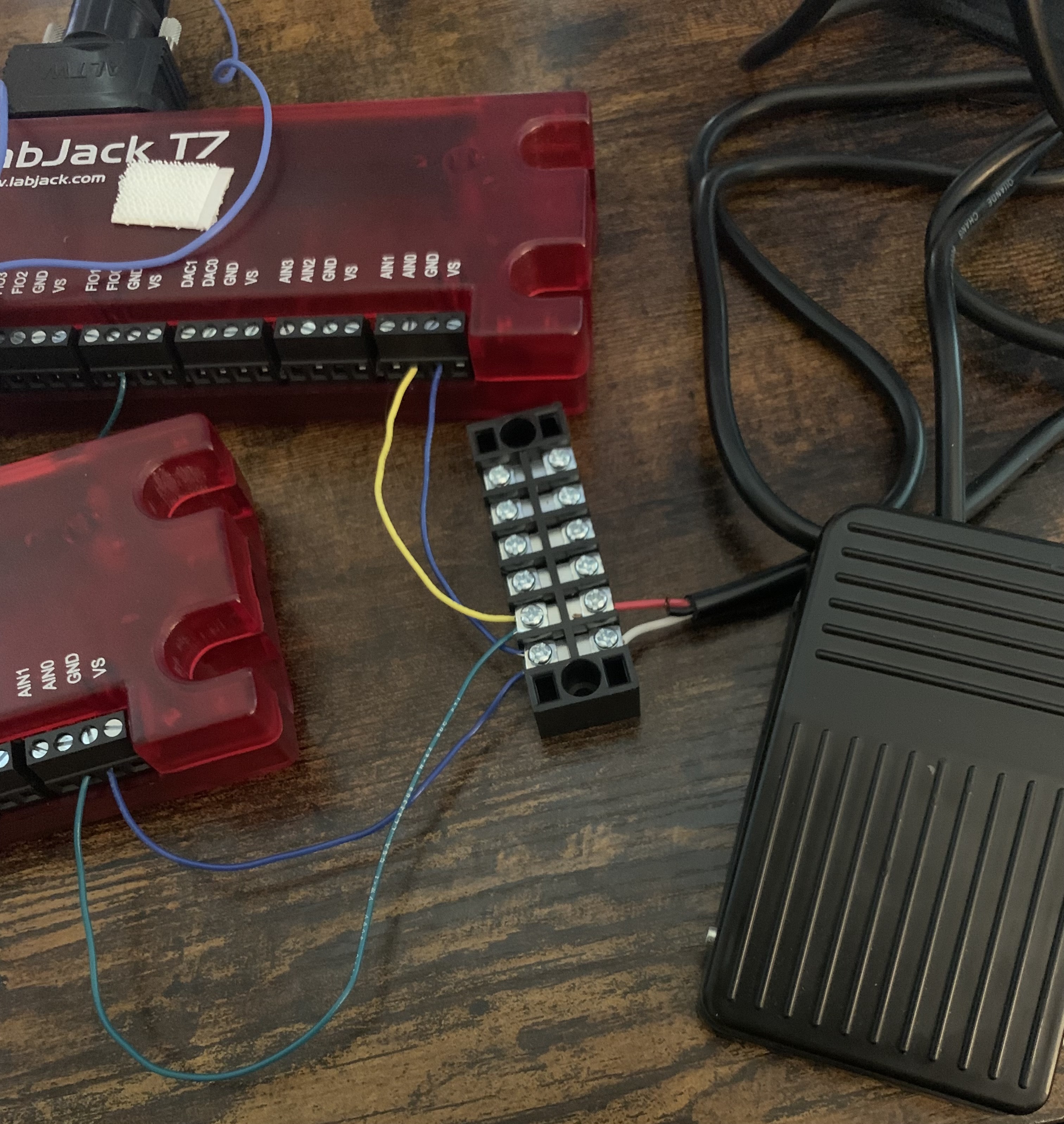
Hi, I have external clocking set up for use between multiple labjacks using one as the master producing a 50khz PWM wave at 50% duty cycle. I read 25k data points every 0.5 seconds from the LabJacks. Right now for testing purposes I have it set up by splitting a foot pedal into two signals going into each labjack as shown in the attached IMG1.
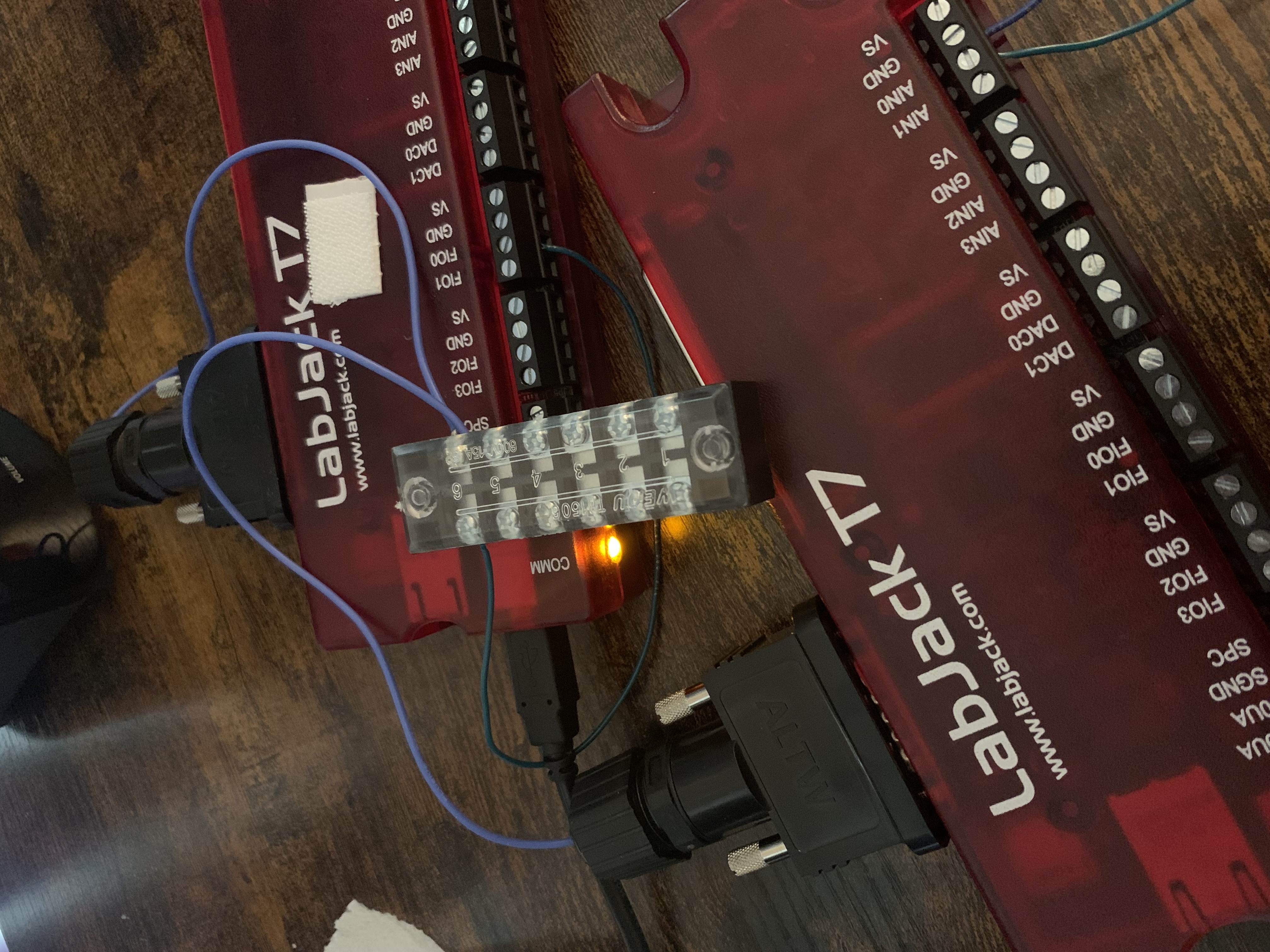
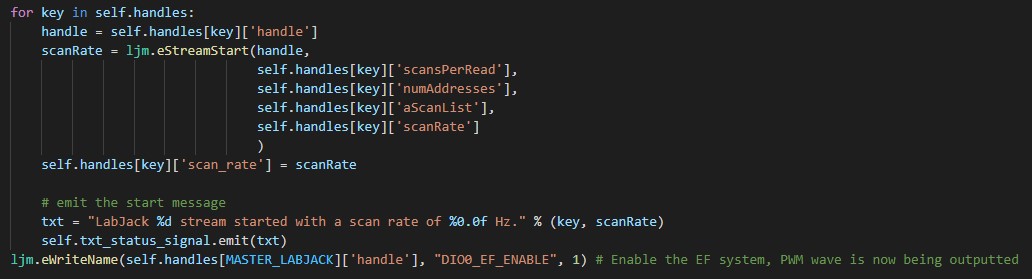
I have the code set up in this order: 1.) Set up the pwm wave as shown in IMG2. 2.) Start the stream for each labjack as shown in IMG3. 3.) Enable the pwm wave as shown in IMG3.
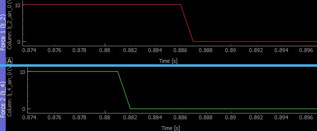
However I am finding that when plotting the data I collected on the same timeframe, the labjack that had its stream started first tends to show events such as pressing the push pedal slightly later than the one that started second, as shown in IMG4. If I swap the order they start in, the new labjack that starts first will be behind the other one. This delay slightly changes each time I run them, but it tends to be ~0.002-0.006 seconds.
I don't understand why this is happening... the one that started sooner should not be getting more scans than the one that started second since I didn't enable the pwm wave until after they were both started. Shouldn't they both have the same number of scans taken at the exact same times?

.png%3Fitok=PHGBxf6M "EEV Blog Reviews LabJack T7-Pro & Software Tools")


.jpg%3Fitok=B1YcuDFK)
.png%3Fitok=Ybt-OlgU "LabJack + JEDI One Can Create a Powerful Distributed DAQ Ecosystem")
To me, it is unclear what exactly is happening, so I would recommend doing some more tests.
You could potentially see extra edges, and therefore extra scans, on one device if there is noise in the clock signal. To minimize that risk, I would recommend starting by testing with the devices next to each other, with all external connections removed besides the clock line, grounds between devices connected, and some signal you generate on both devices to test the behavior you are seeing. Ideally, you would only use device signals, such as switching a voltage from a T7 DAC output, for your test signal.
How are you generating the timestamp information? If you are using some system timer, that could be adding a time error that isn't obvious.
You should be getting the same number of scans if you start and end stream at the same time, with the same clock. If you start stream before generating clock pulses you should be starting at the same time. I would recommend trying a test using stream burst to ensure you get exactly the same number of scans.
I switched over to using a square wave produced by DAC1. I found something interesting regarding when it becomes misaligned.
On 50kHz sample rate streaming (and 50kHz PWM wave), there seems to always be some skipped scans at the start of the stream and then it is fine for the rest of the stream. If you look at the 2 50kHz sample images I posted, you can see that the streams are aligned until they skip, and then when they return from skipping they become misaligned. I tried this many times and it appears to always be after the initial skipped scans that it becomes offset like this. I also tried doing this on 10kHz and never had any issues, there were no skips and the data was aligned. Then I tried doing it on 20kHz and found that sometimes it would skip and become misaligned, and sometimes it would not skip and remain aligned for the whole stream, as shown in the 2 20kHz sample images attached.
I am not sure about the misalignment issue, but the skipped scans may be due to overhead starting stream. Skipped scans mean that the device stream buffer is filling up. Instead of overflowing, the device does autorecovery, which replaces samples that cannot be added to the buffer with a dummy value (-9999). You get dummy values until the buffer is empty enough to start appending real data again. Usually this is caused by consuming samples too slowly on the host software side, but can also be caused by heavy processor load bottlenecking the data transfer to the host.
I did a test where I started stream, delayed around 1 second, then enabled the PWM for the clock and that did a good job of eliminating skipped scans. For that to work for you, you would need to set the stream receive timeout to a value bigger than your delay and also need the ability to start the external clock after starting stream. Here is some code summarizing what I have setup for that test:
Does the above help resolve your issue?
I will try that solution once I have access to the second labjack again, that seems like it will take care of the skips at the start. I do still need to take care of the misalignment issue since sometimes it still randomly skips mid-stream when running on a weaker laptop. So there's no ideas as to how skipping could cause misalignment like that? All I am doing is looping through reading each LabJack and sending the 25000 data points from each LabJack to the plot starting at 0 seconds and incrementing by 0.00002 seconds per point for 50kHz until I stop the stream... if skipped scans just get replaced with -9999 I don't really understand how it becomes misaligned, it should just have some random -9999s scattered in the data but there should still be the same number of points, so I guess I will start by using a stream burst to check if some extra points are being added in somehow or some scans are being missed.
Unfortunately, we are not sure what is causing the misalignment you are seeing. We are planning to do some more tests to reproduce the issue and will follow up when we have more information to share.
I am trying out the above method of introducing a delay after the stream starts before enabling the PWM wave but its causing some weird problems for me.
For reference, I have provided images of the relevant code I am working with.
If I just add a 1sec delay to my original code, I run into this error: LJME_TRANSACTION_ID_ERR (this is with a STREAM_RECEIVE_TIMEOUT_MS shorter than the delay time).
Then when I change that timeout to 0 (no timeout), as done above in the example, the code gets stuck on the call to enable the PWM wave at the bottom of streamStart.jpg, I always receive the "Trying to enable PWM" statement, but can never reach the "Enabled" message, and it doesn't seem to throw any sort of error.
Now if I try changing that timeout to something a little bigger than 1sec, eg 2000 ms, then that same line of code to enable the PWM wave returns, but at really random times, and then doesn't seem to work because I just continously get NO_SCANS_RETURNED and never any real data. I tried this 3 times quickly and the first time it took 5 seconds for the PWM write call to return, one time it took 1 second, and one time it took 48 seconds.
If I simply remove that sleep statement at the beginning after the stream is started, everything works like normal again, but of course I still get a few skipped scans that cause misalignment.
The final weird piece of behaviour I found occurs when stopping the stream. I found that once I changed the MS timeout to 0 (no timeout), my button to stop the stream no longer worked, and what I found was that the ljm.eStreamStop(handle) call was doing the same thing... never returning, but only if it was called after I made the call to disable the PWM wave with ljm.eWriteName(handle, "DIO0_EF_ENABLE", 0). Once I started making that call to disable the PWM wave after I stopped the stream, it started working again.
Also I am not sure if this makes any difference, but I am not running a set number of pulses like in the above code snippet, just enabling the PWM wave when I press start and disabling it when I press stop.
Update: I found one new thing after writing this. I tried changing the amount I'm delaying by instead of 1 second like above, and I found that if I do 0.01-0.05 seconds, it works normally but still skips, if I do 0.06-0.07 seconds, it works perfectly no skipping, and then once I do 0.08+ seconds it does what I was talking about before.
Please check that your firmware and LJM version are up to date. I would recommend using our beta LJM installer and firmware 1.0292. Firmware can be updated using the device updater tab of Kipling. The following page has our LJM installers:
https://labjack.com/support/software/installers/ljm
As a baseline, please try a similar test with our external clock example. The only modification necessary should be changing the timeout on line 122 and moving lines 135 and 136 to run after eStreamStart and your delay. This works without stalling for me:
https://github.com/labjack/labjack-ljm-python/blob/t8/Examples/More/Stre...
How are you setting the start condition? Are you certain there couldn't be something going wrong there and do you have a way to test the condition is getting set correctly?
What OS and connection type are you using? We have heard of similar issues with eStreamStop when using external clocked stream. on macOS, it is a known issue with libUSB. The issue should not occur with an Ethernet connection type. Unfortunately, outputting pulses until after you call eStreamStop or using Ethernet are the only workarounds we have at this time.
I'm using windows and USB connection. I don't have enough ethernet ports on my computer to use multiple labjacks all on ethernet unless I buy some sort of adaptor.
I tried upgrading from release LJM to beta LJM as you suggested and the problem seems to have disappeared. On a one second delay with STREAM_RECEIVE_TIMEOUT_MS of 0 the call to enable the pwm wave is now succeeding and it is working properly.
I am now trying it again with no delay at all and it seems that the beta version of LJM is also now preventing those initial skips too, so the delay may not even be necessary.
Another way to prevent auto recovery is to increase the stream buffer size. The default stream buffer size is 4096 bytes and can be increased to up to 32768 bytes by writing the desired size to the register STREAM_BUFFER_SIZE_BYTES. The value must be a power of two e.g. 2048, 4096, 8192, 16384.
What channels were in your scanlist when you were seeing the misalignment issue?
When just testing this and trying to get it to work I am only using the square wave signal from DAC1 of one labjack, splitting it, and reading it from the AIN0 channel on both labjacks, so my scanlist is just AIN0 on both labjacks being scanned at 50kHz.
The actual machine I will use this with is read by 4 labjacks, the first two both just read AIN0 at 50kHz, one reads AIN2 and AIN3 at 50kHz, and the last one is reading DIO0_EF_READ_A at 50kHz. When testing on the machine, I am using the same code with a few small differences and still see the allignment issue. The differences being 1.) I am not including the labjack reading both AIN2 and AIN3 in the external clocking, when reading those two channels each at 50kHz I tend to run into SCAN_OVERLAP errors on external clocking so since that data is less important in terms of being synchronized, it just runs on its own internal clock. 2.) I added this line
ljm.writeLibraryConfigS('LJM_STREAM_DIGITAL_AUTO_RECOVERY_ERROR_DETECTION_DISABLED', 1)
to the machine code because of the labjack that only reads DIO0_EF_READ_A since otherwise I get LJME_DIGITAL_AUTO_RECOVERY_ERROR_DETECTED and I can't add a different channel that can't return 0xFFFF in front of DIO0_EF_READ_A because then it will start scan overlapping just like the one with AIN2 and AIN3, but this data needs to be synchronized so this was the only option I could find.
So far since upgrading to the beta LJM I have not had any skips and I haven't been able to make it skip so I can't tell if it is still misaligning on each skip.
The way LJM knows where to insert dummy data is by finding where there are 0xFFFF in the stream packet (specifically looking at the first sample of the first channel in a scan). Putting a register that can return 0xFFFF under normal operating conditions as the first stream channel eliminates LJM's ability to know exactly where it needs to add dummy samples. You need to make sure you are not going into autorecovery when you disable the autorecovery detection.
You should be able to stream an AIN and one DIO_EF_READ_A register at a 50kHz scan rate. However, you must have the stream resolution index set to 1 and AIN range configuration set to ±10V. Also, what DIO_EF are you streaming? Many of the input DIO_EF require edge processing that runs at a lower priority than stream. Due to the lower priority, the effective edge rate is limited to around 20000 edges per second while streaming.
We are using DIO0_EF_READ_A to read a rotary encoder in quadrature mode. Although, I am not entirely sure it is necessary for us to use quadrature in our application, since the rotary encoder only ever spins in one direction. It just counts down from 65535 counts to 0 and then jumps back up to 65535 again over and over, as shown in the attached Encoder Ex.jpg. So what you are saying above is that reading at 50kHz is sort of pointless since the labjack can only process edges at 20kHz max? I would prefer to keep reading the encoder at 50kHz if possible since it is much nicer to work with all the data if they are all at the same scanrate, but if it is pointless and it will work better at a lower rate I can change it/ increase that labjack's external clock divisor.
The wall I am up against right now is that if I put another channel such as AIN# in front of DIO0_EF_READ_A on the scanlist on external clocking mode at 50kHz, then I get SCAN_OVERLAP errors at random times, sometimes immediately, sometimes it takes up to ~40 seconds, but it always happens. Before I was running with these settings (AIN_ALL_NEGATIVE_CH = ljm.constants.GND, AIN_ALL_RANGE = 10, STREAM_SETTLING_US = 0, STREAM_RESOLUTION_INDEX = 0), so I tried changing the resolution index to 1 as recommended above, but it didn't seem to make a difference.
If I remove the channel and have only DIO0_EF_READ_A, then I get this error (LJME_DIGITAL_AUTO_RECOVERY_ERROR_DETECTED) every time it resets the counter... I'm not entirely sure why it suddenly goes into auto recovery every time it resets since when the AIN channel is in front of it I never get any skips, so it must not be going into auto recovery in that case.
Then in order to avoid that error, if I set LJM_STREAM_DIGITAL_AUTO_RECOVERY_ERROR_DETECTION_DISABLED to 1, then of course I no longer get that error, but I get some weird behaviour, as expected of course, every time it resets/where that error was thrown before. I have a piece of code counting -9999 values to tell me if skips ever occur, and when this happens it usually ends up telling me there was ~20 skipped scans each reset but I don't really trust that since AUTO_RECOVERY is disabled so its not filling the -9999 values correctly, but I am getting some.
So I'm not really sure what's going on here, but the only version right now that doesn't error out is when I disable auto recovery error detection and have some weird behaviour when the encoder resets. Hopefully that isn't misaligning that data from the rest like before when I was saying that skipping always misaligned my data and then I prevented skips by updating my LJM but I don't really have a decent way of telling whether the encoder data is still lined up with the force data so I don't really like this solution.
The other weird thing that is causing problems is whenever the solenoid powering part of the machine we are taking data from powers on or off, it causes a scan overlap in the labjacks. We have completely isolated the labjacks and their connections from anything connected to the solenoid and replaced the previous clock line wires with better shielded ones, yet it is still causing overlaps, so I'm wondering if something like that could possibly be causing some electromagnetic noise that is still reaching the labjacks and causing overlaps. Another related issue that I experienced suddenly the other day is that for a while it started scan overlapping more frequently, even for just the two force sensors that don't typically cause any problems and then a little while later it stopped doing that. I didn't change anything important in the code, the only things that I think could have changed was moving around the labjacks and cables a bit, and that it was pouring rain outside during that time... if that could cause any interference. So I think something was probably causing interference/noise in the clock lines causing it to overlap so I'm wondering if there are any recommended ways to set up the wiring such as using diodes or even better shielded wires to try to eliminate this issue?
Sampling at 50kHz could still make sense, especially if that is what you need for the AIN sampling. An interrupt based feature like quadrature will miss edges if there are more than 20000 edges per second from the encoder; my main point was that the edge rate of the feature is more limited while streaming. You could use a high speed counter instead of quadrature if you are only tracking one direction and that does not have any such edge rate limit.
I am not sure about the scan overlap when trying the DIO_EF and AIN. Does this happen both with an external clocked stream and regular internally clocked stream or just externally clocked? If you are seeing a lot of edges from your encoder you would be putting a pretty heavy load on the processor. I would recommend trying a similar test with a high speed counter instead of quadrature.
I would want to take a look at the circuit on an oscilloscope. As an alternative to an oscilloscope, you could connect the signal to an AIN and run a single single channel at 100kHz.
If the line is just noisy, there are some different things you could try. If the device is otherwise floating, you could try connecting GND to an earth GND instead. You could try moving where the shield is grounded. Since it seems like a scan overlap probably means you are seeing extra edges, I would want to try adding a low pass filter. Inductors/TVS diodes/chokes could help with EMI suppression.