
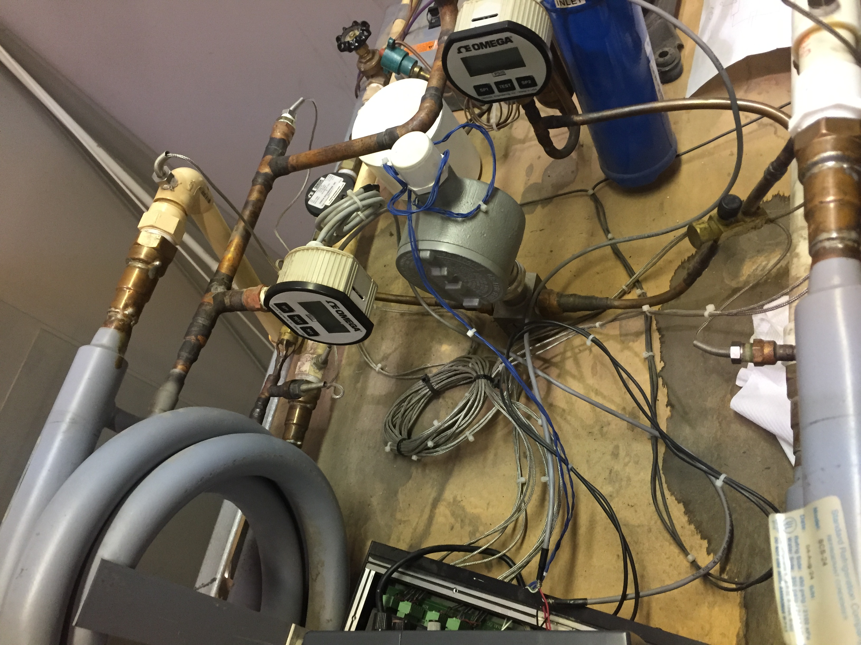
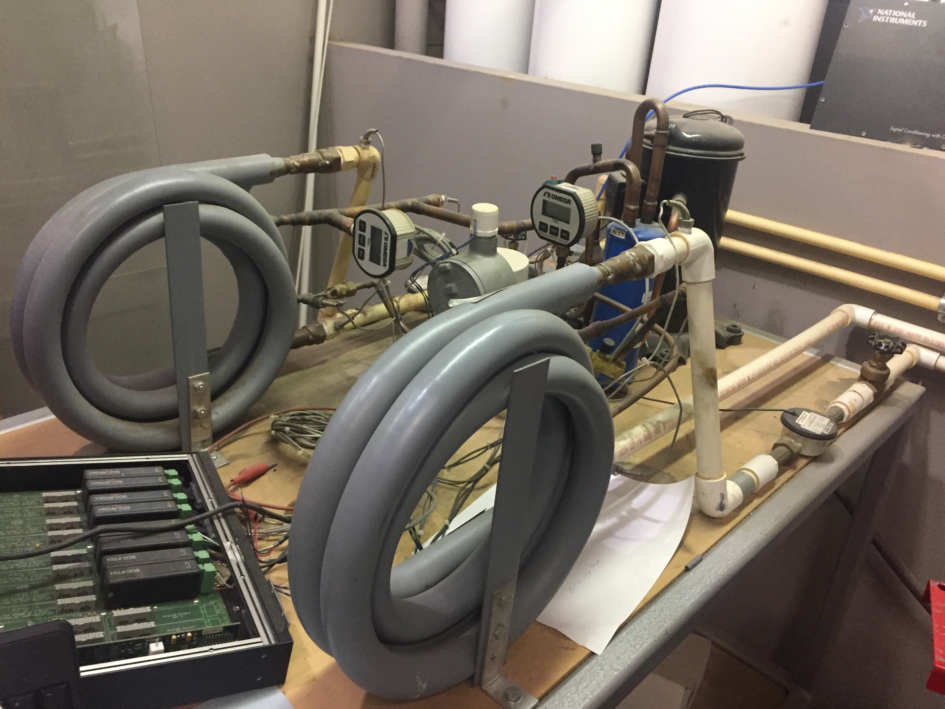
To start off I am new to labjack, and I am required to use this software for this project. I basically have to get readings on labjack for 4 RTD's, 3 flow meters, and 2 pressure transducers. This is for a refrigeration system, and one of the flow meters includes a signal conditioner. My question is how do I go about setting this up? I know the basics for setting up the RTD's is by using a wheatstone bridge along with an op amp, but I don't know how to set it up for 4 RTDs, much less with the Pressure transducers and the flow meters.
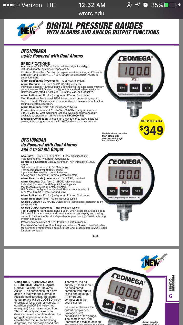
I know the RTDs are 100 ohm resistance, www.omega.com/pptst/FTB4600.html is the website for 2 of the flow meters, and http://www.omega.com/pptst/FTB9500.html is for the flow meter of the refrigerant along with http://www.omega.com/pptst/FLSC60.html for the signal conditioner of the refrigerant. The pressure transducers info is located in the attachments, it's the DPG1000DAR version.
Attached are pictures of the system and of the Pressure transducer info. What I am struggling with is understanding how to set up the circuit, since I need to have a prototype with a basic breaboard setup before a final product is designed. I can not use anything such as LJTick, I have to build it on a breadboard. Also would everything have to be in parallel to ensure the voltage is distributed to everything equally? If so are there any sources that could aid me in setting up this project, and is a U6 labjack all that I need? I don't believe a U3 would be enough but I'm unsure as I've mostly dealt with Mechanical Engineering and electrical is not my strong point. Is there anything I have to be careful of when setting it up? Has something similar been done before? I have done plenty of research but that only gets me so far, and I have yet to find something that incorporates this many devices into one labjack interface. I realize that this is a lot to read through but any help is appreciated! Once readings are obtained using labjack I will be using Java to develop a GUI to show the temps, pressures, and flows of the system. Thank you!

.png%3Fitok=PHGBxf6M "EEV Blog Reviews LabJack T7-Pro & Software Tools")


.jpg%3Fitok=B1YcuDFK)
.png%3Fitok=Ybt-OlgU "LabJack + JEDI One Can Create a Powerful Distributed DAQ Ecosystem")
Will follow up with another post about hardware. As for software, start with LJControlPanel and LJLogUD so you can use known software to make sure your hardware is working, and then go to Java.
Using Java on Windows you will be interfacing with the UD library. The documentation for the UD functions is here:
https://labjack.com/support/datasheets/u6/high-level-driver/function-reference
The design of the UD library, though, is such that the functions are pretty simple. They all are just pretty much different way of sending requests and reading results:
https://labjack.com/support/datasheets/u6/high-level-driver/overview
So generally what is more important is all the IOtypes and constants that you use, and the best documentation for those is in Section 4.3:
software/examples/ud/java
https://labjack.com/support/datasheets/u6/high-level-driver/example-pseudocode
The one exception to all that is the easy functions. If you are just doing basic writes and reads, 1 channel at a time, then the easy functions are an easy way to do that:
https://labjack.com/support/datasheets/u6/high-level-driver/example-pseudocode/easy-functions
Start here for Java examples:
https://labjack.com/support/
RTD:
RTDs are likely the most difficult temperature sensor to use:
https://labjack.com/support/app-notes/temperature-sensors
That app note suggests the LJTick-Resistance for RTDs. Another option is using the 200UA current source, but with 4 RTDs in series you will want to add a big cap from 200UA to GND. Yet another option is to use a bridge circuit, and for that see the following forum topic ... in particular post #13:
http://forums.labjack.com/index.php?showtopic=4376
Pressure:
Your pressure sensor appears to provide a 4-20 mA signal:
https://labjack.com/support/app-notes/measuring-current
Flow:
FTB4600: You need to provide the 6-16 VDC power supply. Information about he output signal is pretty sparse, but sounds like an NPN output (switches between high-impedance and low).
FLSC-6x: Do you have the 61, 61, or 64?
Hey sorry for the late reply, but I have the FLSC-6x model 64. Also I think I'm going to go with the bridge circuit for the RTDs. Is there a certain resistor value I should use when setting up the Wheatstone bridge? Or is it fine as long as the three resistors used are the same values since the post you referenced mentioned using 1000 Ohm bridges. The picture I'm attaching is what I thought of doing for the RTDs. You also mentioned putting the RTDs in series, would I still have to do that for the 4 RTDs I have to get readings off of or can I just do the Wheatstone bridges with the op amps separately?
Also for the pressure transducers on the bottom of the link you sent, https://labjack.com/support/app-notes/measuring-current , it mentions "In this case, if SGND is used (rather than GND), a direct connection (0 Ω) should be good." does this mean I can just set it up as the circuit in Figure 2 is shown? That being said do I have to use the Shunt? Or is there a way around this.
As for the flow sensors can they just be a direct connection, or do they also require a Wheatstone bridge?
Thanks for your help!
FLSC-64: You can power this with the 5 volts from the LabJack and it will then give you a nice 5 volt square wave that you connect directly to DIO.
FTB4600: If it is NPN output like it sounds, you can direct connect to the LabJack. You might want to add a 4.7k pull-up. This signal should then connect directly to a DIO, and you will also need a connection from the power supply ground (or signal negative) to LabJack GND.
https://labjack.com/support/app-notes/open-collector-signals
3 pulse signals from flow sensors: These will go to a counter or frequency measurement timer on the LabJack. What is the pulse rate range (0 to n pulses/second) you expect from these 3 signals?
http://forums.labjack.com/index.php?showtopic=1105
RTDs with bridges: Typically you use resistors that match the active element so you get a balanced bridge. That would suggest using 3x 100 ohm resistors to complete each bridge. The downside to that is that your bridge will draw substantial current, so your excitation source needs to be able to handle that much current and you might have to worry about self heating of the RTD element due to that current. 1000 ohm RTDs with 1000 ohm completion resistors would be better.
In your bridge circuit you show an amp. Note that this will have to be an in-amp, not an op-amp, and you have to figure out how to handle the negative voltages. With the U6 you do not need the amp for your bridge as the U6 & T7 can handle raw bridge signals.
With the bridge method you will make a bridge for each RTD. The series thing was just for the current source method:
https://labjack.com/support/datasheets/t7/200ua-and-10ua
For your current signal, yes Figure 2 seems right. For the "Shunt" I suggest a 240 or 250 ohm resistor. For the "0-100 ohm" resistor I would say that yes 0 is likely fine, and 0 just means a wire.
Another question is how fast do you need to scan all these signals? For example, perhaps once per second you want all this info?
I believe the range of the signals for one of the flowmeters(the one that measures the flow of the freon) is 40 to 1000 hz , also once per second for the signals sounds like a good starting point. I don't think I will need it any faster.
Is there a reason why I have to use an in amp and not an op amp? An in-amp is just comprised of op amps right? Well unfortunately I can not change the RTDs so I'll have to use what we have. So if I was using a U3 then I would need this amp? I ask since I'm not entirely sure how to properly set up the in amp even after looking up the differences. But if I did set it up would the U3 be able to read it?
FLSC-64: Finished that, I got good square waves.
Also I'm working on the pressure transducers, seems like it'll work! (:
At your pulse rates you could consider counting or timing. Look at forum topic 1105 for some thoughts that might lead you to a preference.
Are you using a U3? It has 2 timers and 2 counters, so you would have to use a combination of timers and counters to handle your 3 pulse signals. The U6 has 4 timers and 2 counters so it could use timers for all 3 signals. Either way I suggest you do initial testing using the test panel in LJControlPanel to confirm operation before you try it in Java.
An op-amp is single-ended input and single-ended output. An instrumentation amp is differential input and single-ended output. You get a differential signal from your bridge so you need to use an instrumentation amp.
Yes if using the U3 you need to use an external in-amp to amplify the small differential signal you get from a bridge. The U6 has an in-amp built-in.
Yeah I am currently using a U3.
For the RTDs I found that set up above, but I am not sure how I would set up the in-amp with that two wire set up. I would think that I would use the following in amp along with the two wires. Note that the R gauge would be my RTD in this case.
Since I am not familiar with this concept I do not know what resistors to use for this set up. Or where the RTD would be connected to, and where the output would go in the labjack U3. Also what would be the best type of op amp to buy and use for this set up? How do I incorporate the in-amp with the wheatstone bridge? I assume it would go where the two wires are coming out of the first figure, and that would give you an output voltage difference and a ground and those would be connected to the labjack U3? Meanwhile the wires from the RTD connect to the beginning points of the two wires extending from the wheastone bridge?
How do I figure out what type of gain I want, and what values for the resistors I should use on the in-amp? Is the reason why I can't use a difference amplifier because of the error in measurements? Also would it be better to use a two op amp INA or stick to three? If you could help out with these steps I should be able to order the parts and get started on building a test circuit. Thank you for all of your help so far! I'd hope I could get a U6 if the budget allows and that would simplify this so much more but I'll have to wait and see on that so meanwhile I have to test it on the U3 to prove that it works.
I'd like to make a correction, it seems that is a three wire 100 Ohm platinum RTD, and it was previously powered via a 1 mA excitation source.
The file attached shows what was prevously used, one RTD was attached to channel 1, 2 and 5. While the other was attached to 2, 3 and . With a wire connecting 4 aqnd 6 together.
Image 2454 shows how they were attached and image 2453 shows what each channel meant.
Since you are trying to understand the basics, don't worry about a 2-wire, 3-wire, or 4-wire RTD. The extra wires are just duplicates so just think of them all as a 2-wire RTD. You can just use 1 wire from each side of the RTD, or better yet twist together the duplicates.
If you want to use the NI signal conditioner that is great. I assume it give a high level voltage output you can connect to the U3.
If you want to use a bridge for your signal conditioning, then first you need to make a complete bridge. See the first couple paragraphs of post #1 here:
http://forums.labjack.com/index.php?showtopic=4376
For thoughts on excitation for the bridge see item 1 in post #13.
You then need to send the bridge output through an in-amp and then send the output of the in-amp to the U3. Here are a few options:
1. Build your own in-amp out of multiple op-amps. The hard way for sure.
2. Buy an in-amp chip.
3. Use the LJTick-InAmp:
https://labjack.com/support/datasheets/accessories/ljtick-inamp
https://labjack.com/support/datasheets/accessories/ljtick-inamp/appendix-d
https://labjack.com/support/datasheets/accessories/ljtick-inamp/appendix...
In one of the pictures I showed how it had three wires, 2 going into the in amp, and one for the excitation source. Which two of the 3 would I use to plug in my wheatstone bridge in place of the resistor? I would assume it would be the power one and one of the other two? Do I have to twist two wires together, and if I do which ones. This is the final step I'm at, I have my set up for a two wire configuration done and this is all that's left. I'd like to thank you for all the help so far!
Look at the diagram near the beginning here:
http://instrumentationtools.com/difference-between-2-3-and-4-wire-rtds/
The 3-wire RTD simply has 2 wires on one side of the resistor and 1 wire on the other side. The wire that is by itself you have to use. On the side that has 2 wires you can use either or both together.
If you are not sure which 2 wires are connected to the same side, use a DMM to measure resistance and see which wires have 0 ohms between them rather than 100 ohms.
Sorry for bumping this thread, but I am also working on this project and am currently comparing the Labjack U3 and U6 for use on this project. While looking through the example java file AllIo for the U3 and U6 I noticed that the example code includes the ability to use a counter or timer, but only if there are less than 8 analog inputs. The U3 code explains the reason why (essentially the way the code/loops are written), but saw no explanation for the U6. My ultimate question is this: is it possible to use a timers/counters on the U6 if there are more than 8 analog inputs? I've included the java codes I am referring to.
Yes, you can use 8 or more analog inputs and timers/counters on the LabJack U6. It has four 14 dedicated analog inputs and 20 dedicated digital I/O. Timers/counters use digital I/O lines and can start on channels 0-8 (FIO0-7, EIO0).
The LabJack U3-LV has 16 flexible I/O which can be either analog input or digital I/O lines. The LabJack U3-HV has 4 dedicated analog inputs and 12 flexible I/O. Timer/counters can start on channels 4-8 (FIO4-7, EIO0) which are flexible I/O lines. You can use 8 or more analog inputs and timer/counters on the U3, but there are more limitations on what lines can be used.
Codewise, the "numChannels <= 8" is a code limit in those examples and for simplification, and not a hardware limit.
For more device details take a look at the U6 and U3 datasheets:
https://labjack.com/support/datasheets/u6
https://labjack.com/support/datasheets/u3