
Hi.
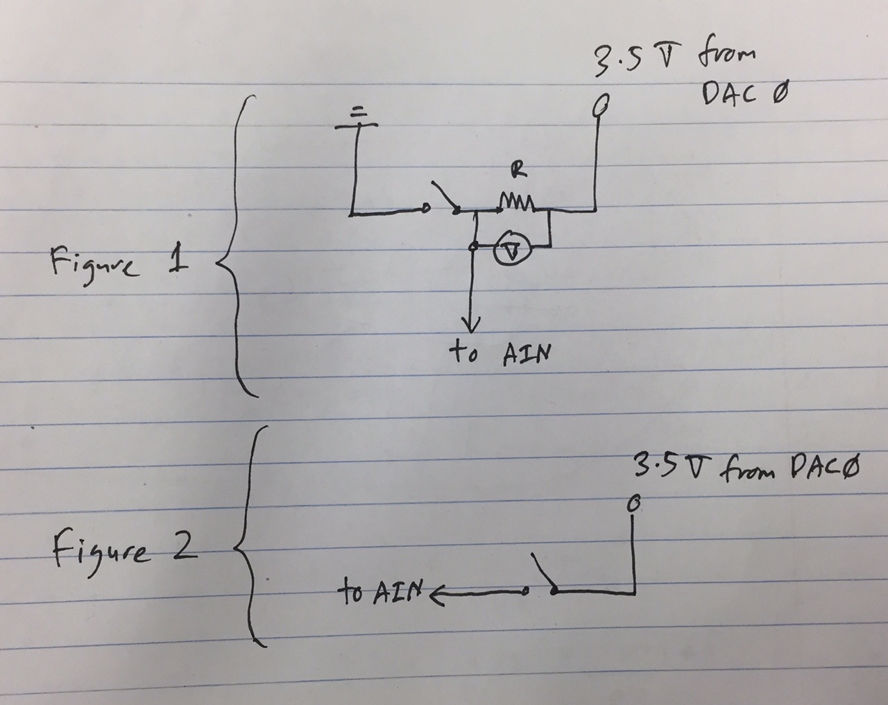
I am currently trying to use the AIN to read voltage of a conductivity probe. The conductivity probe acts like an ON/OFF switch. The power supply comes from DAC0 at 3.5V. The setup is shown in Figure 1 the attached file.

So my question is, using the setup in Figure 1, the AIN will constantly read the 3.5V from DAC0, and this means that my switch has no purpose. Does this mean that AIN also acts like a ground?
Can I just connect DAC0's 3.5V to the +ve of the switch, and connect the -ve of the switch directly to AIN as shown in Figure 2? In this case, can I assume that it is grounded?
Thank you for your help.
File Attachment:

.png%3Fitok=PHGBxf6M "EEV Blog Reviews LabJack T7-Pro & Software Tools")


.jpg%3Fitok=B1YcuDFK)
.png%3Fitok=Ybt-OlgU "LabJack + JEDI One Can Create a Powerful Distributed DAQ Ecosystem")
The AIN channels do not act like a ground. They are high impedance inputs and will not be able to sink any current. It sounds like you are mis-interpreting how your conductivity probe works. You said that it acts like a switch, Can you measure its resistance with a DMM when it is ON and again when it is OFF?
In Figure 1, it looks like there is an extra component other than a resistor and your switch (conductivity probe), what is it? If your conductivity probe acts like a switch, I would expect you to only need a resistor in series with the switch, I can't think of another component that you would need.
Hi.
The conductivity probe is basically a probe that switches ON when it is in contact with water, and switches OFF when it is in the air. What I wanted to do is to measure the voltage across the resistor.
This is the actual circuit that I want to build. But I am not really sure how I can read the voltage V1, V2 and V3 using AIN. Initially I connected the AIN inputs in parallel to the resistor, but it reads 3.5V even when the switch is OFF.
Can you suggest something that I can do?
Thank you for your help.
It would be useful if you could use a DMM to measure the resistance of you sensor when on and also when off.
If your sensor really acts like a switch, you can just connect it to FIO4 and GND:
https://labjack.com/support/app-notes/mechanical-relays-switches
When the switch is open the internal 100k pull-up holds FIO4 HIGH. When the switch closes that creates a connection to GND that pulls FIO4 LOW. Just watch FIO4 (configured as digital input) in the test panel in LJControlPanel to see if it works.
So is there any possibility that I can use AIN as a voltmeter?
(As in the Figure 1 that I posted)
Yes, your circuit in post #3 is fine also. You will use differential AIN pairs to measure the voltage the resistor. When the switch is open, no current flows, and the voltage will be 0. When the switch is closed, current will flow and most voltage should be dropped across the resistor and you will measure about 3.5V.
An improvement to your circuit would be to put the resistor on the low side of the switch such that one end of the resistor is connected to GND. Then you just use 1 AIN to measure the single-ended (versus GND) voltage on the other side of the resistor.
So what size resistor should you use? To properly answer that question you need to use a DMM to measure the resistance of your sensor under different conditions, but guessing without that info I would say 1kohms.
Sounds like maybe you are trying to make a voltage divider circuit where your switch is the unknown resistance R1:
https://labjack.com/support/app-notes/signal-voltages-out-range
I think for my case I am going to do the one in Figure 1 but I need to do 5 parallel probes. In this case, I will need 10 AIN, and I am using the stream mode because I need one probe to be 10kHz. I couldnt find the reference for using stream mode with differential AIN. Can you please direct me to any reference related to what I am doing?
And I assume I have to lower my sampling rate now since I am using 10 channels instead of 5 channels?
To do a differential reading in stream mode you just use LJ_ioADD_STREAM_CHANNEL_DIFF rather than LJ_ioADD_STREAM_CHANNEL. See the pseudocode here:
https://labjack.com/support/datasheets/u6/high-level-driver/example-pseu...
In fact, many people always use LJ_ioADD_STREAM_CHANNEL_DIFF and if they want single-ended they set x1=199.
The max scan rate for 10 channels is 5 kscans/second:
https://labjack.com/support/datasheets/u6/operation/stream-mode
... but you are not doing 10 channels. If you stream 5 differential channels you are using 10 analog inputs but it is a 5 channel stream.
Looking at your drawing in post #3, if you would just flip the position of the resistor and switch you could then do single-ended readings. Put the resistor on the low side and the switch on the high side.
I ended up using the circuit in post #3, and I used the low side of the resistor connected to my AIN. When the switch is OFF, AIN reads around 3.5V and when the switch is ON, AIN reads around 1V (I use a 1MOhm resistor). The input voltage is from U6's DAC0.
The AIN for one channel needs to be 10kHz, and it needs to be for 5 channels.
So this works fine for me when I am using stream wait mode SLEEP for one channel. Once I add the second channel (I am using AIN0 and AIN1), at 10kHz rate per channel, I could not get the same reading of 3.5V for ON and 1V for OFF. Both signals become constant around -9V. I tested using the same setup but using a very low sampling rate (around 10 to 100) and it works fine.
So basically what I am saying is that I get what I want to read when I am using 10kHz for one channel, or low sampling rate if I use 2 channels. But when I increased the sampling rate for 2 channels, it stops to work. I assume that the circuit works fine since it works for low sampling rate. Do you have any idea what happened?
Thank you for your help.
Your source impedance (1M) is too high:
https://labjack.com/support/app-notes/SettlingTime
Tables 1 & 2 are for the T7 but the U6 AIN system is almost identical.
If you would like more help with your measurement, please disconnect your sensor and use a DMM to measure the resistance of your sensor under different conditions of interest to you. Once we know what sort of resistance values you are trying to measure we can consider options of how to do it.
Thank you LabJack guy!! You are the best!